Aug 2001
Malaysia's newest power project, the Manjung Power Plant, is located on the West coast of Peninsular Malaysia, 260 km north of Kuala Lumpur in Perak. It will also be the largest coal fuelled power station in the country. TNBJ, the national power utility, awarded a turnkey design and construct contract to a joint venture between Alstom and Peremba with the civil engineering works being carried out by Leighton Contractors Malaysia.
The power plant
project is being built on a 'Power Island' just off the
coast to allay environmental concerns. The recently
reclaimed island is to be the site of the 3 x 700 MW
plant. One of the most time critical structures of the
project was the pump house and associated water pond.
However, its design was complicated by the geology of the
site. Although not far from the mainland, the reclaimed
sand platform sits on soft marine clays overlying recent
alluvial deposits, making it complex to excavate the 20 m
deep sea water intake and pumping station in future. The
initial design envisaged a sheet pile cofferdam. However,
from a practical point of view the numerous strut levels
would have made excavation and construction costly and
very time consuming. Specialist geotechnical contractor
Bachy Soletanche Malaysia developed an alternative scheme
for the construction of the pump house which was adopted
by the engineer in the ultimate design.
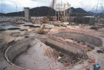
Figure of eight shaft -61 & 59m diameter
with depths 30-40m
The solution consisted of using a diaphragm wall
retaining wall to form the water pool and the pump house
without any need for internal strutting. This was done by
creating a figure of eight shape, with one section for
the water pool and the other slightly larger section for
the pump house proper. The figure of eight shaft
consisted of two touching circles which are 61 m and 59 m
in diameter with panel depths of 30 to 40 m deep. The use
of the diaphragm wall to contribute load bearing capacity
meant that only 31 barrettes foundations, 60 m deep, were
required to found the heavy pump house structure and
equipment. This also contributed to the savings in time
as initially eighty large diameter bored piles had been
anticipated. The diaphragm wall and foundation work was
completed in about 12 weeks between June to August 2000.
This allowed the rapid excavation of the water pool and
pump house and the construction and installation of the
critical mechanical equipment.
However, while the design is very efficient, the
construction of any circular shaft needs to be carried
out in accordance with strict tolerances to ensure the
highest quality of work. Due to the nature of the
circular retaining structures, their efficiency derives
from the hoop action of the compressive forces. This
means that the accuracy of the diaphragm wall panel
joints must be controlled to ensure that the compressive
forces are transmitted between the two structural
elements. Any deviation between the panels reduces the
surface area available and therefore the capacity of the
hoop structure to resist the forces. To ensure compliance
with the strict 1:200 tolerances, Bachy Soletanche
Malaysia used the highly accurate KS3000 hydraulic grab
to excavate the diaphragm wall panels and barrettes.
Incorporated in the grab is an inclinometer that gives
real time readout in the operator's cab showing the
verticality in both planes. Any deviation outside can
immediately be corrected. The KS3000 equipment is used
regularly in Malaysia, Indonesia and Singapore but
normally for its high productivity rate. This was one of
the first instances it was used in Asia for such
tolerance critical work. The compressive forces discussed
above come together for both shafts at the two
intersection points — another quality critical
point.
Apart from the delicate excavation of these two Y shaped
panels, the reinforcement cage detail was very important.
For ease of construction and installation, the 'cage'
consisted of four elements, a triangular central cage and
three normal reinforcement cages for each leg'. All four
elements had to be overlapping which made for complex
manoeuvring of cranes on site." To enable the
accurate placing of all this reinforcement, the
triangular or 'spider' cage was placed in the
intersection of the Y with its legs' extending to each
side of the panel. Next the three normal reinforcement
cages were lowered into each leg of the Y, interlocking
with the triangular cage, which acted as a guide. Once
all the cages were safely and accurately installed in the
panel, universal beams were then placed in the pump house
and water pool sides of the Y panel to further reinforce
this 'pinch' point. Concreting was undertaken using three
tremie pipes which were filled together to ensure the
highest quality finish. In addition to these two special
panels, there were a number of other special panels for
the water intake tunnels and the pipe work leading to the
power station from the pump. To ensure structural
integrity around the future openings, specially designed
reinforcement panels were installed into the wall. This
innovative design and construction method is the first
such application in Southern Asia, according to Bachy
Soletanche. Similar but smaller projects of this nature
have been carried out by Bachy Soletanche in Hong Kong
and Korea.
The advantages to the programme and structure were
significant. With the retaining structures being
incorporated into the permanent works, further cost
savings were obtained. Such structures are often used in
Europe for storm water retention as the highly efficient
design and the rapid construction time ensures minimum
disruption to the surrounding properties. The equipment
used incorporates sophisticated electronic and hydraulic
systems, is reliable, and adapted to the works of this
nature. It is a reliable alternative to the Hydrofraise
diaphragm wall cutter for accuracy.
Extract from Southeast Asia Construction.